Showing posts with label Digital Sketchbook. Show all posts

Saturday, 23 May 2015

Having already created the arch for the drain, I wanted to embed it further into the wall I created for it. Although I had already decided not to use bricks to show the texture of the wall, including this on arches would be a little simpler as I could extrude the faces outwards to give the idea of brickwork that would have flowed round the drain.


Selecting all the faces, I could extrude them inwards by scaling them and again to create the illusion of brickwork. Showing the in their baser linear format would give the sharp contour of bricks that would help me keep this subtle texturing.


Using the extruded faces, I selected and moved them outwards from the model to create each individual brick. As the bricks in this model would not be laid the same way as regular bricks, this works quite well. Looking at the wall model for instance, having this technique used would mean all the bricks would be aligned, and structurally it doesn't make too much sense.


I did the same with the inside lip to give a bit more on an interesting look. As I wanted to create a grate this would help later on.


At this point I wanted to crate a hole in the wall for the drain to fit. I combined them and tried to isolate the face, which unfortunately did not work. I tried using Maya's booleans, but not having experience with them, I did not really know which direction to head with them. Knowing what I wanted to create would help with my deduction of tools.


I went back to the Maya forums and looked up how to cut out faces from different objects. Many of the questions posted were slightly different to my own, but it did seem as though I was heading in the right directions working with booleans. Because of this, I went back into Maya and messed around a bit more.


As I worked with booleans, I soon realised that, much like Adobe Illustrator, using two objects that will intersect, after cutting them away, the objects disappear. In that if you were to place a cylinder on a cube, after using the cutting tool, you would be left with a new shape entirely. Because of this, I duplicated my drain for later on. Knowing it would be deleted in one of the processes, I wanted to have another to use in the new place for the hole.


The first boolean I used was Union. As in the picture below, it has completely removed the section I wanted. This would have been great if it wasn't for the shape it left behind.


The shape left behind was a completely hollow shape with no geometry to it. As below, the hole it being held open by an unreinforced curve. Because of this I tried another.


Using the difference function gave me what I needed. There was a new geometry inside, as well as the faces I could delete on the outside.


Removing the faces from the bottom section allowed me the space I needed to move the drain into place.


Much like before, I came up against a similar issue. Where I had used the boolean function, the object had turned green.


From my experience before, I knew this was easily solved and that the object had just lost it's default material.


Wanting to be sure I was doing the right thing, I looked back over the webpages I had used before and followed the same process I used with the characters face.


Creating a new cube and grouping them should have left me being able to assign the current cube material to the wall.


After combining, the material assignment didn't actually stick. Because of this I had to try another option, being exporting the objects as a whole and reimporting it in place, hoping that it would reassign it the material.


Exporting and reimporting the selection is obviously a lot more of a long winded way of doing things, but in this instance it worked. Following along with the tutorial on the website, I managed to reimport the object in the same place, giving it the default material type in the process. Not only this, but with reimporting it both the drain and the wall had been merged together, allowing me to now have this wall with the drain in place as one complete object.


With the drain now in place, I wanted to create a grate that would cover the drain and not allow creatures in. Using a polycylinder, I increased the height and and decreased the radius to give me a fairly realistic bar shape. Using the duplicate command I could move the new object over, then using the duplicate again command it would create a new object, but with the same transform properties as the original.


Using this tool I could create the basic vertical poles for the grate.


Duplicating and rotating one of the existing poles, I could then begin work on the horizontal ones. Using the same tools as before, I could move the pole into place and begin duplicating.


Creating a rather oversized grate was not so much of an issue as it could be scaled together to fit. Also, because of the ground plane I had made, I could move the grate into place using the plane as the 3rd edge for the poles to sit against. Having the freedom to move the poles sticking through underneath would save me a lot of time as I wouldn't have to match up all the points exactly when positioning it.


Lining up the grate with the lip I had created earlier proved to be the most challenging thing. Using the wireframe mode to sit it in position allowed me to see the construction of the whole object. This is by far the most interesting object I have created so far. Looking at the model as it is progressing, I can see the knowledge I have gained growing and allowing me to play more within the work. Because of this, although I don't think going into the Unity Engine is practical anymore, I do think this is the career path I will end up pursuing. From the short time I have had to work in these types of software, I have been inspired, motivated and challenged during the entire process. This in itself is something I feel is very necessary for me in a working environment. When moving onto my professional practise, I will bear this in mind and follow my progression and approach to companies accordingly. Without challenging myself through this project I would not have realised my love for 3D form and the artwork that can be created. So far this project has pushed me further than ever before, but i'm so very glad I took the leap.


Tuesday, 19 May 2015

Further Developing 3D Assets

Continuing to develop the buildings themselves, I wanted to work a little more on the inside of the structures I was creating. With this, looking at the doorways I had included to this point, I wanted to add more of an interior feel to one of the buildings. Having the entrance designed the way it was, and heavily influenced by the entrance of Helms Deep, I wanted to create an open plan inside space that lead to a very open but narrow walk way inside.

As stated before, as the geometry of the piece I had created had become merged with other pieces, I began create more and more loops to extrude so that I would not have to contend with the complicated geometry. As seen in the image below, the loops were meeting at a point in the bottom of the building. This was not necessary ideal, as I wanted to extrude them upwards they would not extrude straight up, rather out to an angle as if flaring apart.


To counteract this, I instead extruded the longer 90 degree edge that ran next to it. This allowed me to raise up an edge to attach a platform to. The image bwloe shows the bottom lip now handing over the two 45 degree edges.


With a roughed out concept now created for the entrance, I wanted to begin work on the stairs. As I had never created anything like this in the tutorials before, I wanted to see if i could work on my own and create something interesting. Using a cube I scaled it up to the height I wanted and began to add loops.


The edge loop tool has a unique feature in that the user can add as many edges as they like with the multiple edge tool, keeping them at equal distances from one another. This would be very helpful in the creation of steps as they would hopefully have been created for someone to each transcend them.


Having the basic shape created I was able to select the faces I didn't want and delete them. From here, I could extrude the new open edges inwards and merge them as I did with the castle previously.


Setting the handles to the middle allowed me to scale the edges from a new pivot point. Each extrusion tool had two different ways of moving the new edges; by world, or by object. Changing the picot point to objects allowed me to drag the edges into the object horizontally instead of out.


Using the same technique as before I was able to merge the vertices to create a solid edge upon which I could manipulate the vertices to make it look a lot more worn and beaten.


With the new edge established in this direction, I could add another loop to the edge in order to create a kind of rail for the edge. With the new faces created from this loop I could extrude them upwards to create this new ledge.


As with the sketches I wanted to establish the different levels through the integration of separate buildings. Using the cylindrical polygon I could change the subdivisions to create a more hexagonal shape that looks something a lot more like my sketch. Having the interior walls match the exterior shape gave the the idea of these different levels being connected by more than just stair wells, but having a ground plane that slanted upwards and merged with the mid level platform.


I began to look at texturing of the model as a whole. As my intention is to texture the model rather realistically I wanted to introduce bricks that would allow me to slowly phase out the basic shapes. The more I began to concentrate on this area, the quicker I realise that this approach was very very impractical. Shaping and moving each individual brick was far too time consuming and did not allow me the freedom to actually create when I spent more my days laying bricks down.


Although the bricks were swiftly thrown out, they did allow me a look into the world of slicing objects. In the image below I wanted to make this brick fit with the others that surrounded it. In order to do this, I had to slice the bottom off. With no obvious way to do this whilst exploring the interface, I went back to the forums to try and find something that may work.


According to many users, this version of Maya had done away with the "Interactive split tool" and had now only included it through scripting. Using the script editor, I could bring up this tool and use it as need be.


The script editor works much like a command script editor in a CAD program, in that you can input coordinates of commands, and at the push of a button it processes them. Not only does this work with transformational properties, but it can also work in the selection of tools. As Maya uses these commands to create everything in the program, every movement or manipulation is assigned its own property.


Using the Interactive Split Tool I was able to slice the object just where I needed to.


Moving on further with the bricks, the practicality of the procedure had just been completely eradicated. At this point after one tower I thought it was about time to pack it in. Although it does look very good the way it is, looking like something one would see in an actual game, it would take far too long for me to use this over the entire model.


Moving onto the walls at the front of the piece, I wanted to create something a lot more simply than I had up until this point. Using a polycylinder with 3 sub divisions at the top, I deleted the faces in order to make a curved wall. Reducing the sub division width allowed for a more rigid wall to be produced. I could then manipulate this further as I did with the original walls and create something stylistically similar.


 Matching the height of the original walls, I was able to offset the new ones a little to create interesting depth.


Deleting the extra faces helped maintain the width I had already created with the two front facing sides.


With the base walls established, I wanted to recreate the stairs for the other side. By selecting the already created stairs and mirroring the geometry, I was able to create an exact replica to surround the entrance. Not only does this give it an interesting aesthetic, but it gives the walls practical application and the potential to be fortified. 


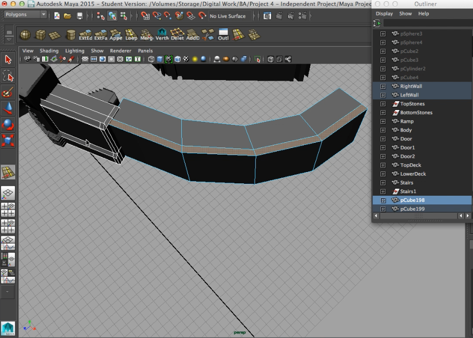
Adding more loops to the walls allowed for the same style to be created throughout. By extruding these faces up and lowering the front edges, I could create a sharp angles edge that gives more of an idea of fortification.


With the basis of the mid level established, I thought the natural progression would be a ground plane. Having wanted to introduce some gradual stairways to either side of the entrance, I thought the best thing to do would be to introduce a gradual lift in a plane below. By adding a polycylinder and splitting it much like the creation of the outer walls, I was able to begin creating this base.


Raising the faces at the side helps prepare for the model of the stairs later on.


Much like with the technique I used before, I applied this knowledge to creating a flared set of stairs for the inside of the entrance. Using a polycube to create the basic shape I could extrude faces to fit the model and give a more practical feel to the inside of the creation.


One of the main things I wanted to include in my piece was intricate arches. Again using the polycylinder, I could flip it and cut the faces to create the basic shape.


From here, extruding down would give me the ability to scale the faces outwards and give a very refined look.


With this new technique, I could begin playing with them in the hope of creating some interesting cover to fit into my model. This image below shows a stairwell I was trying to create to fit the back of the model, wherein the stairs would be undercover reaching the mid level. The more I created of this piece the more I didn't necessarily see how it fit the style of the rest of the piece. For this reason, I think it best to scrap it and move on.


Much like with the character model, I ran into problems with extruding. In the image below, the normals on this extrusion have been reversed for some reason. Although I spent a lot of time trying to rectify this issue before, knowing what caused it last time helped me resolve the issue this time. Although this time I did elect to delete the entire piece and start again, knowing the issue first hand saved me time in the process.


Using the arch technique I was able to create more believable doorways around the environment. Just with this simple cylinder extrusion I was able to again extrude the faces to create the illusion of brickwork.


Through working with the piece I decided it best to add another level to the top. Although not in the original concept sketch, I thought it would be fun to play around with some new techniques in order to create a new and interesting level. Extruding a polycude and shaping the end into a thick taper gave me the idea that this could be a grand hall at the top, with a arched doorway to the end and pillars surrounding it for support.


Placing it to the back of the mid level really brought to life the idea I had had. Having this one of the biggest and most interesting parts of the piece would really give a sense of magnitude to the over all environment. If I could include some kind of prop for scale later on, I think I could really work with something that could be huge.


Using the same technique as before I went about making a drain for the far left wall as illustrated in the concept sketch.

Adding two loops to the centre I could use the inside faces as a perch for me to later include a grate.


Extruding these faces inwards gave me the lip I would need when creating the metal bars.


At this point I thought it best to move onto changing the plane the environment was sitting on. As time pressed on and I kept running into new challenges, my thoughts of moving into the Unity Engine looked further and further away. Because of this I wanted to make precautions if that happened. Through briefly looking up how to make a mountain terrain in Maya, I was directed to a brush set in Maya that is similar to ZBrush. Although it is criticised as being a slight rip off, it did give me an idea.


Through following a few tutorials and playing around in the software I was able to create the basic contours of a mountainous terrain. The brushes themselves were very limiting, but gave me the freedom I needed to continue creating in Maya. 


Trying to replicate what I had laid out in my concept sketched gave me a better sense of scale to work with in the image. Now that working in Unity seemed a bit more daunting, having this new ability in Maya gave me back the time I needed to carry on working.


After creating these basic shapes, I was left with the letter "S" all over the terrain. After a quick search it appeared that inside of maya, all the transformations for a single object are kept until the object is either deleted, or the objects history is cleared. These S's remained because they are a modification command. As with things like the interactive split tool, the S stands for softmod, the command used in the script editor. Through realising this, it occurred to me that I hadn't deleted the history for any object since I had started the project.


Through deleting the history of everything, the program began to speed up again and felt fresher. Not only that, but all the S's disappeared from the screen. Looking up how to view a rendered panel in Maya, one user suggested using lighting to see the contours of certain objects. With this advice, I added a directional light to the scene to really see how this new terrain would fit with my model, and honestly looking at it like this, I cannot believe I have come so far in such a short space of time.